
NXP LPC1768 ARM Cortex-M3 Board
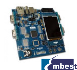
You can use the Cortex-M3 based LPC1768 Evaluation Board to generate and test application programs for the NXP LPC17xx microcontroller family. The LPC1768 Evaluation Board introduces the new NXP LPC1760 family of ARM Cortex-M3 processor-based devices, allowing you to create and test working programs for this advanced architecture, it has a wide range of interfaces making it a great starting point for your next Cortex-M3 project. With this hands-on process, you can determine the hardware and software requirements for current and future product development.
The LPC1768 Evaluation Board ships with the LPC1768 device that is a superset of several other device variants of the LPC17xx microcontroller series. The LPC1768 Board contains all the hardware components required in a single-chip LPC17xx system.
- Hardware Specifications:
- USB 2.0 Full Speed Interface
Standard USB connectors for USB Device, USB-OTG, USB Host and UART via USB on the LPC1768 board for applications requiring USB communications.
- Dual Serial Ports
Standard DB9 connectors are on the LPC1768 for both of the LPC1700's serial ports. Your application may use either of these ports.
- Dual CAN Ports
Standard DB9 connectors are on the LPC1768 board for applications requiring CAN communications. Your application may use either or both of these ports, or they may be disabled with a configuration jumper.
- LCD Display
A detachable, 240x320 TFT, color LCD display. You may use this graphic display device to show real-time debug and program status messages.
- MicroSD Card Connector
A MicroSD Card connector for developing applications requiring access to MicroSD Cards.
- Joystick
A 5-position joystick. Your application may use this to control port pin input.
- LF Amplifier
An LF Amplifier on the LPC1768 connects the D/A output of the LPC1700 device to a speaker. You may use this LF Amplifier to generate sound.
- Analog Voltage Control for ADC Input
An adjustable analog voltage source is on the LPC1768 board for testing the Analog to Digital output feature of the LPC1700. A configuration jumper enables and disables this feature.
- JTAG and Cortex/ETM Download and Debug
The LPC1768 board incorporates both a JTAG interface and a Cortex Debug + ETM interface. When coupled with the ULINK2 USB-JTAG adapter, the Serial Wire JTAG interface allows flash programming and debugging. With the ULINKPro adapter, the Cortex Debug/ETM interface allows flash programming and instruction trace debugging.
The connectors on the LPC1768 evaluation board provide easy access to many of the LPC1768's on-chip peripherals.
- USB 2.0 Full Speed Interface
- Block Diagram:
The hardware block diagram displays input, configuration, power system, and User I/O on the board. This visual presentation helps you to understand the LPC1768 board components.
- Technical Data :
- Software and Examples
Embest provides plenty of software examples for this evaluation board, all in source code. These software examples can be debugged under the popular Keil MDK (Microcontroller Development Kit) environments, making practical use of the board's peripherals.
| Parameter | Description |
| Supply Voltage | 5V DC (provided by the USB bus of a PC) |
| Supply Voltage | 5V DC (provided by the USB bus of a PC) |
| Supply Current | 65mA typical, 120mA maximum |
| XTAL Frequency | 12 MHz |
| Microcontroller | NXP LPC1768 |
| Peripherals | 2 RS232 Interfaces 2 CAN Interfaces 1 Ethernet Interface 1 JTAG Interface 1 ETM Interface 2 Cortex Debug Interfaces 1 LCD Display 1 USB Device/Host/OTG Interface 1 Analog Output (connected to speaker by default) 1 Analog Input (connected to potentiometer by default) |
| Board Size | 119mm x 119mm (4.68 " x 4.68") |